CloudBlue Commerce API (DRAFT)
Table Of Contents
Information Architecture
Information architecture (IA) is the structural design of shared information environments.
In this document:
Purposes
In APS applications, IA contains compiled data collected and built in the previous design steps. In accordance with the MVC concepts, data models are defined in the application backend, that is in its provisioning logic, whereas the user interface (UI) part is implemented in the application frontend, that is in the presentation logic.
IA design contains the following steps:
UI design - analyze and structure the UI content used by certain personas in certain context
Backend services design - define inheritance, relations, properties, structures, and operations of the APS types declared in the application resource model.
To aid in design, architects can use 3rd party modeling software specially developed for IA.
Design Steps
IA should define the following IA systems:
Labeling systems are the ways we represent information, such as the level of terminology considered appropriate for the target audience. For example, should UI use the terms “VE” and “virtual environment” or the “VPS” and “virtual private server” are more appropriate?
Navigation systems are the way we move from one piece of information to another when that information is presented to us. On the server creation screen, for instance, you could use the Next button to get to the next page, or you could cancel the process by pressing another button.
Searching systems are the way we search for information, such as entering words in a search engine or scanning for terms in a numbered list. For example, in the search box on the screen displaying a list of servers, you could type multiple words to narrow the results and get closer to the server you want to reach.
Other components in IA in our case are the requirements to APS types and backend services.
Taking the above into account, there are several basic steps in organizing IA for an APS application:
Taxonomy - define a controlled vocabulary and locations so the major content, UI structure, and navigation elements are always identified consistently.
Chunk and outline your content to have logical units with a consistent modular structure outlined as hierarchical trees.
Draw diagrams that show the UI structure and rough outline of pages with a list of core navigation links.
Analyze your system by testing the organization interactively with real users; revise as needed.
Taxonomy
Taxonomy is the science and practice of classification. In information architecture, a taxonomy is a hierarchical organization of content categories, using a specific, carefully designed set of descriptive terms.
In this section, we will touch some aspects of taxonomy.
Controlled Vocabulary
To be consistent and clear for users, the application UI should have a consistent set of terms and names in the form of a controlled vocabulary that must become a fundamental element used throughout the application UI and documentation.
The template for the controlled vocabulary may look as follows:
Name and aliases |
Abbreviation |
Comments (optional) |
|---|---|---|
Virtual private server
Server
|
VPS |
|
Memory
Random access memory
|
RAM |
Measured in MB |
… |
… |
… |
Location
In the platform, there are the following locations for embedding application UI.
Provider control panel (PCP) has a number of places to plug application UI:
Application instance tab
Left-hand navigation panel
Dashboards
UX1 provides the following built-in integration locations:
Top level in the left-hand navigation panel
Home dashboard
Integration points in User manager and Domain manager
UX1 provides the placeholder in the left-hand navigation panel for service users
UI Structure and Content
Chunk and Outline
UI structure must be presented by a diagram containing screens with navigation links between them.
Chunk the UI content into logical units with a consistent modular structure and outline the UI content as hierarchical trees. This influences the static structure of navigation trees. In control panels, usually it is not necessary to have a tree with too many levels. Usually up to 3 level hierarchy is quite sufficient. Keep the following principles:
Create a separate hierarchical layout for each location.
Separate different categories of scenarios into different branches. For example, in a cluster of servers, general configuration of servers is separated from configuration of the firewall and load balancer. Respectively viewers with logs are better to separate from both of the above.
Consider first the screens with general data and place them on top. Screens with more specific and detailed data can be placed at a lower level. For example, the list of servers is used more often than other screens.
Scenarios may contain a common task. This task can be implemented in a screen that you should place on an upper level, since your users will search for it more often than for other screens.
Meet your users expectations based on mental models . Users try to find some components in a way similar to ones used in other applications.
Try to avoid two marginal cases:
Very shallow structure with too many branches on top
Very deep structure with one to two items on each level
APS allows you to link screens in a sequence or in a hierarchy. Combination of both types is allowed as demonstrated in the following diagram.
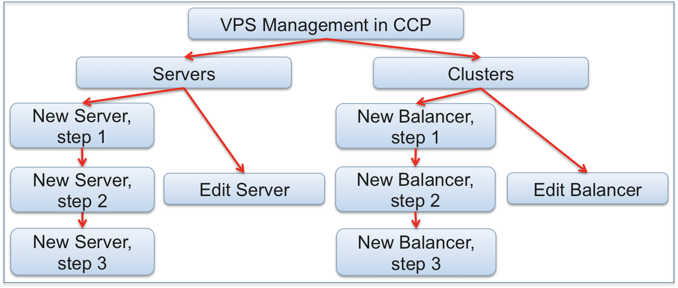
Such a diagram contains all application screens used in the particular location.
There are some techniques for implementing this design step such as card sorting and whiteboard sessions.
Screen Content
For each screen, implemented later as a view on the development phase, define its content that users will view or configure along with navigation controls to go to other screens.
The outcome is a table with UI entities for each screen.
Entity |
Type |
Default value |
Description |
|---|---|---|---|
Purpose |
String |
“This is a 1st view in the VPS creation wizard” |
Not visible anywhere - just for the developer |
Title |
String |
“Virtual private servers” |
Title on top of the screen |
Unique ID |
String |
“servers” |
Declared in meta and used for navigation |
Offer link |
Link |
“offer” |
Required link with an offer used by the VPS |
Host name |
String |
“” |
The name of a VPS |
… |
… |
… |
… |
Next |
Navigation control |
N/a |
Navigates to the second step of the wizard |
Backend Service Design
Design Process
For each APS type declared in the resource model, define the following data in accordance with the Type Definition document.
Inheritance (the “implements” element)
Properties and structures
Relations
Operations (methods and arguments):
CRUD operations
Custom operations
Outcome
Tables presenting a list of properties, structures, relations, and operations for each APS type
Optionally diagrams presenting resource hierarchy if they simplify the development process
Example
In the Offer Management demo project, the APS application resource model looks as follows.
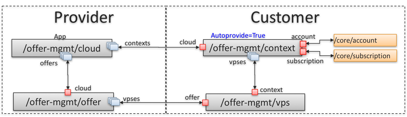
The obtained service allows the customer to manage the structures and properties of a VPS in accordance with this diagram:
From this input data, you can compile the following tables that describe the information architecture
of the /offer-mgmt/vps APS type (not all properties are presented below).
Inheritance
Type name |
Description |
Type ID |
|---|---|---|
|
Mandatory implementation of the core resource |
Relations
Name |
Relation Type |
Related APS type |
Backward relation |
Description |
|---|---|---|---|---|
|
required, singular |
/offer-mgmt/context |
|
Allows the application executables to find all VPSes in the subscription through the management context |
|
required, singular |
/offer-mgmt/offer |
|
Needed to get limitations specified by the related offer |
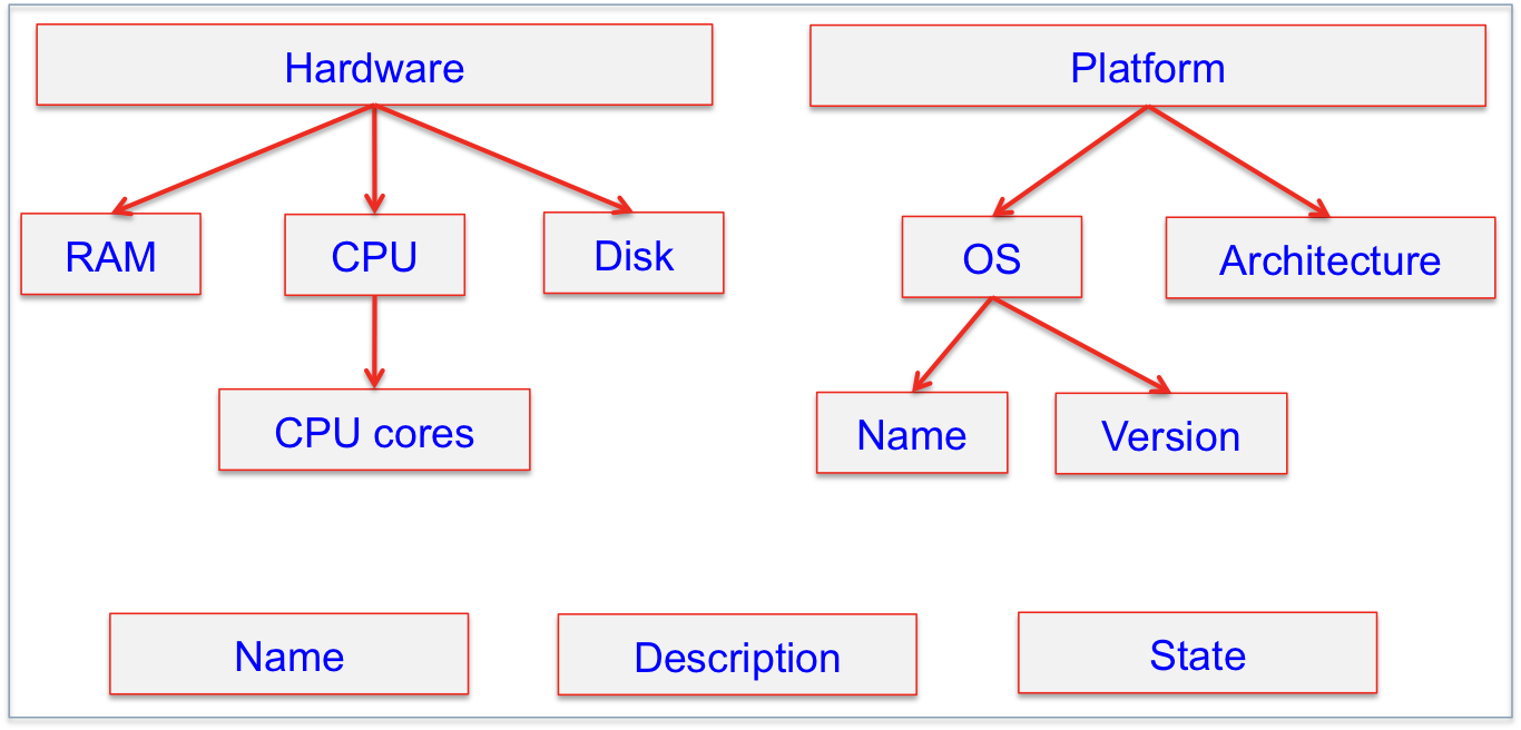
Properties and Structures
Property |
Type |
Description |
|---|---|---|
|
String |
VPS name |
|
String |
Detailed description of the VPS |
|
Boolean |
VPS state, either stopped or running |
|
Integer |
Number of CPU cores assigned to the VPS |
|
Integer |
RAM space allocated to the VPS |
|
Integer |
Disk space allocated to the VPS |
|
Structure |
Contains the |
|
Structure |
Contains |
Operations
Roger should identify all needed operations by analyzing user scenarios and present them all in a table similar to the following:
Name |
Arguments |
CRUD or custom |
Description |
|---|---|---|---|
|
|
CRUD |
Provisions a VPS on the application side using its native API.
No arguments are needed, since the APS controller sends all VPS properties
in the body of the REST request.
|